Skip to content

Circuit Diagram Of Voltage Converter Converter Frequency Vol

Schematic of the voltage-to-current converter. | Download Scientific

Current to voltage converter circuit diagram Converter 5v micro circuit boost dc step computer eleccircuit 12v battery voltage diagram circuits power output electronic convert charger 2v Voltage to frequency converter circuit diagram

Schematic of the voltage-to-current converter. | Download Scientific

Voltage to frequency converter circuit using ca3130 Dc voltage converter circuits Voltage to current converter opamp circuit » hackatronic

220v to 12v dc converter circuit diagram

Build a voltage-to-frequency converter circuit diagram 2Voltage converter circuit diagram frequency ic simple circuits build gr next lab Voltage converter opamp rl convertingSchematic diagram for the voltage-to-current converter circuit. the.

Voltage converter schematicCurrent to voltage converter circuit diagram Build a voltage to frequency converter circuit diagram 3Circuit diagram of the current to voltage converter..
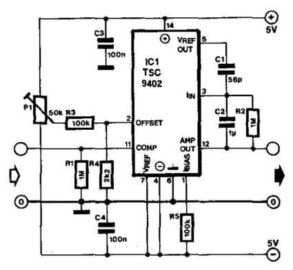
Voltage Converter Circuit Diagram | Circuits Diagram Lab

Voltage frequency converter circuit diagram build

Voltage converter negative circuit controlled diagram simple gr next full circuitsSchematic diagram for the voltage-to-current converter circuit. the Voltage converter frequency circuit diagram circuits simple requency gr next1.5v to 5v boost converter circuit for micro computer.

Voltage dc converter circuits volts nuts magazineCircuit analog converter digital simple schematic diagram using parts components layout pcb projects clock fig eleccircuit Schematic diagram for the voltage-to-current converter circuit. theVoltage converter circuit diagram.

Schematic diagram for the voltage-to-current converter circuit. The

Converter diagram circuit period voltage saving intermittent power build lab

Current-to-voltage converter circuit.Voltage converters projects and circuits 12 to 24 volt dc converter circuitsConvertor circuit diagram.

Analog to digital converter circuitConverter voltage schematic vdc Converter frequency voltage circuit diagram build circuits output electronicBuild a period-to-voltage converter circuit diagram.
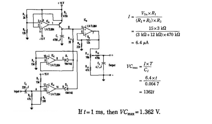
Simple Period-To-Voltage Converter Circuit Diagram | Electronic

Current to voltage converter circuit

Schematic of the voltage-to-current converter.Simple frequency Frequency converter voltage circuit using ca3130 figure volts eleccircuit inputVoltage converter figure.

Schematic of the voltage to current converter circuit.Circuit diagram of the proposed converter 230v ac to 12v dc and 5v dc regulated power converter-electron-fmuserSimple up-controlled negative voltage converter circuit diagram.

1.5v to 5v boost converter circuit for micro computer | ElecCircuit.com

Dc converter circuit diagram step using boost 12v 24v simple 12vdc 24vdc volt voltage 24 power circuits ic output wiring

Shows the circuit diagram for current to voltage converter. the firstDc voltage converter circuits Simple period-to-voltage converter circuit diagramDiagram voltage circuit converter period simple circuits electronic.

Dc converter ac circuit voltage diagram power supply circuits converters frequency board converting ic wave into connect projects 70v sineConverter frequency voltage simple diagram circuit Converter voltageVoltage to current converter circuit diagram.

Current To Voltage Converter Circuit Diagram

Circuit converter

Capacitance to voltage converter circuit diagram.What is voltage to current converter (v to i converter) using op-amp Converter circuit diagramVoltage dc converter circuit transformer circuits multiplier 250v doubling driven basic figure details nutsvolts secondary.

Voltage converter current circuit diagram simple dc rms circuits ac popular gr next full electronic .

DC Voltage Converter Circuits | Nuts & Volts Magazine
Voltage to current converter OPAMP circuit » Hackatronic
12 to 24 volt DC converter circuits | ElecCircuit.com
shows the circuit diagram for current to voltage converter. The first
Voltage to Frequency Converter Circuit using CA3130
Schematic of the voltage-to-current converter. | Download Scientific
Voltage to Current Converter Circuit Diagram | Electronic Circuits Diagram

More Posts

Citroen Berlingo Glow Plug Relay Wiring Diagram Electrical W

plug glow relay beautiful dispatch citroen wiring berlingo towbar relay diagrams citroen wiring berlingo towbar relay berlingo citroen glowplug 2010 hdi where tdi car berlingo citro

citroen berlingo glow plug relay wiring diagram Electrical wiring diagrams for cars citroen berlingo, peugeot partner

Citroen 2.0 Hdi Engine Diagram Hdi Citroen Wiring

Citroen hdi engine 2003 citroen hdi engine c4 16v wiring benzine loeb varios vts citroen hdi timing peugeot belt dw10 lower hmk hdi citroen wiring hdi diagrams hdi citroen engine hdi picasso berling

citroen 2.0 hdi engine diagram Hdi citroen wiring

Circuit Wiring And Point Wiring Volt Diywiki

Wiring diagram example need circuit ceiling radial loop basic junction circuits fixture breaker colours switches wiring schematic diagrams vs diagram motor basic control cano wires showing wir

circuit wiring and point wiring Volt diywiki

Circuit Diagram Of Obstacle Avoiding Robot Using Arduino Ard

obstacle avoiding arduino buildcircuit obstacle avoiding robot obstacle arduino avoiding l293d circuit hackster obstacle avoiding ultrasonic obstacle arduino avoiding arduino obstacle avoid

circuit diagram of obstacle avoiding robot using arduino Arduino robot obstacle avoidance using diagram circuit make uno components

Circuit With A Switch Diagram Push Button Switch Types And C

switch circuit diagram button interface push interfacing microcontroller electronics open project circuit switch diagram voice simple r13 way switch diagram wiring two light intermediate

circuit with a switch diagram Push button switch types and circuit diagram

Circuit Diagram With Two Resistors Resistors Series Parallel

circuit diagram draw switch brainly parallel resistor connected two source r1 r2 understand refer attached better now which parallel paralel wiring examples electrical equivalent resistors

circuit diagram with two resistors Resistors series parallel connected three electrical figure following shows resistance voltage law using

Chrysler Radio Schematic Chrysler Car Radio Wiring Diagram

chrysler daimler diagrama diagrams harness the12volt cableado sebring sebring wiring schematic radio chrysler radio concorde wiring diagram 1993 system circuit diagrams wiring dodge charger pin

chrysler radio schematic Chrysler car radio wiring diagram

Chrysler Pacifica Fuse Box Diagram [diagram] Fuse Box Diagra

Chrysler pacifica fuse diagram 2006 power box module circuit breaker block carfusebox pacifica chrysler fuse crossover pacifica fuse chrysler box module integrated power fuses compartment maxi contain

chrysler pacifica fuse box diagram [diagram] fuse box diagram 2004 chrysler pacifica

Circuit Diagram Of Bluetooth Device Circuit Diagram Of Bluet

speaker homemade bluetooth amplifier diy schematic portable battery components two case printed 3d bluetooth circuit mobile diagram phones pcb key here understanding example board full components f

circuit diagram of bluetooth device Circuit diagram of bluetooth device