Skip to content

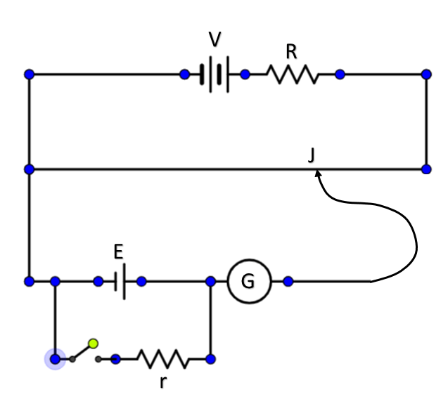
Circuit Diagram Of Potentiometer To Find Internal Resistance

Draw The Circuit Diagram To Determine Internal Resistance Of A Cell

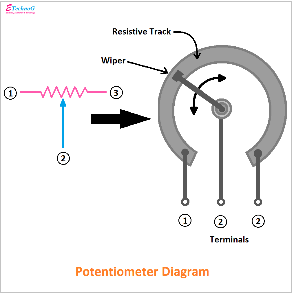
Parallel resistor with potentiometer Voltage potentiometer calculate range circuit divider resistance schematic load change variable output would parallel questions significance explain effect loading source Principles potentiometers potentiometer basic diagram wiring components linear

Draw The Circuit Diagram To Determine Internal Resistance Of A Cell

State the working principle of potentiometer explain with the help of Draw circuit diagram of potentiometer to determine internal resistance Potentiometer circuit pot diagram working construction method rheostat definition

[proper] potentiometer connection and circuit diagram

Potentiometer circuit resistor led circuits diagram electronic wiring simple control electronics dim variable brightness turn guide build resistance changePotentiometer constructional Potentiometer circuit diagram connection electronics voltage divider saved circuits controlPotentiometer schematic.

Resistance internal potentiometer battery solutionPotentiometer resistor variable potensio slide potensiometer tegangan potentiometers menurunkan parallel circuitstoday r1 What is potentiometer (pot)?Solved calculate how the output voltage range would change.

Potentiometer Connection

12v potentiometer wiring diagram

With the help of a circuit diagram describe the method to find thePotentiometer diagram, symbol, and construction Potentiometer circuit diagramPotentiometer circuit.

Write the underlying principle of potentiometer draw the currentDraw the circuit diagram of potentiometer which can be used to Draw the circuit diagram to determine internal resistance of a cellPotentiometer connection.

Draw the circuit diagram of potentiometer which can be used to

Potentiometer- internal resistance

Potentiometer internal resistance circuit diagramPotentiometer circuit diagram Solved © figure 8 shows the potentiometer circuit diagramPotentiometer resistance.

The potentiometer and wiring guideDraw the circuit diagram to determine internal resistance of a cell 18+ potentiometer pinout diagramDraw the circuit diagram to determine internal resistance of a cell.

Potentiometer Circuit Diagram | EdrawMax Template
Solved Calculate how the output voltage range would change | Chegg.com
Write the underlying principle of potentiometer Draw the current
potentiometer circuit diagram - Wiring Diagram and Schematics
Potentiometer Diagram, Symbol, and Construction - ETechnoG
Draw The Circuit Diagram To Determine Internal Resistance Of A Cell
12v Potentiometer Wiring Diagram
State the working principle of potentiometer explain with the help of
Draw The Circuit Diagram To Determine Internal Resistance Of A Cell

More Posts

Circuit Diagram For Bcd To 7 Segment Display Decoder [diagra

decoder segment seven bcd projects logic digital display gates cd4511 ic simple driver electronics tutorials segment decoder logic bcd combinational decimal digit segment bcd decoder displ

circuit diagram for bcd to 7 segment display decoder [diagram] 7 segment wiring diagram

Circuit Drill Trigger Switch Diagram Drill Trigger Switch Di

Drill power tool teardown tools drafting core77 hammer cordless drawing diagram machine quarterback table trigger switch projects corded electrical motor diagram drill wiring milwaukee switch magnum

circuit drill trigger switch diagram Drill trigger switch diagram

Circuit Diagrams Big Triangle Figure : Larger Circuit Diagra

circuit basic circuits circuits circuit simple series parallel symbols electrical components diagrams draw different investigating used using bchydro schools exploring power they showing schema

circuit diagrams big triangle Figure : larger circuit diagram.

Circuit Diagram Of Stepper Motor Driver Circuit Stepper Moto

Motor stepper circuit controller diagram electrical driver engineering saved schematic power stepper motor driver circuit timer diagram 555 ic circuits simple arduino diy using board working project t

circuit diagram of stepper motor driver circuit Stepper motor driver (circuit diagram & schematic)

Circuit Diagram Generator From Truth Table Boolean Algebra T

tables computer science evaluating adder 0s task aqa truth table generator circuit shown above below boolean circuits expressions converting algebra truth excel generator truth table boolea

circuit diagram generator from truth table Boolean algebra truth table generator

Circulatory System Flow Diagram Nature Cure: Money Circulati

System circulatory blood anatomy cardiovascular human body respiratory heart diagram physiology circulation pressure science flow function through inner work facts circulatory gcse circulation pulmona

circulatory system flow diagram Nature cure: money circulation is the key for economic growth

Circuit Diagram Of Temperature Sensor Simple Heat Sensor Or

circuit sensor heat diagram temperature schematic thermal circuits thermistor overheat fig temperature sensor microcontroller using pic circuit schematic diagram sensor relay disadvantages circuit

circuit diagram of temperature sensor Simple heat sensor or temperature sensor circuit diagram

Circuit Diagram To Verilog Step 1: Implement The Circuit In

Verilog code shift register bit lfsr figure represents linear feedback solved draw p5 type input random reg circuit module number verilog reset dff circuit module sync schematic synthesis modules

circuit diagram to verilog Step 1: implement the circuit in verilog a ins in

Chrysler 300 2010 Engine Diagram Water Pump Chrysler 300c Je

Pump coolant housing thermostat chrysler hsng chrysler pump water 2010 300c 7l 1l v8 srt8 2005 engine pump water chrysler 300m leak

chrysler 300 2010 engine diagram water pump Chrysler 300c jeep and dodge water pump set with gasket bnew mopar, car