Circuit Diagram Of Current Transformer Difference Between Cu
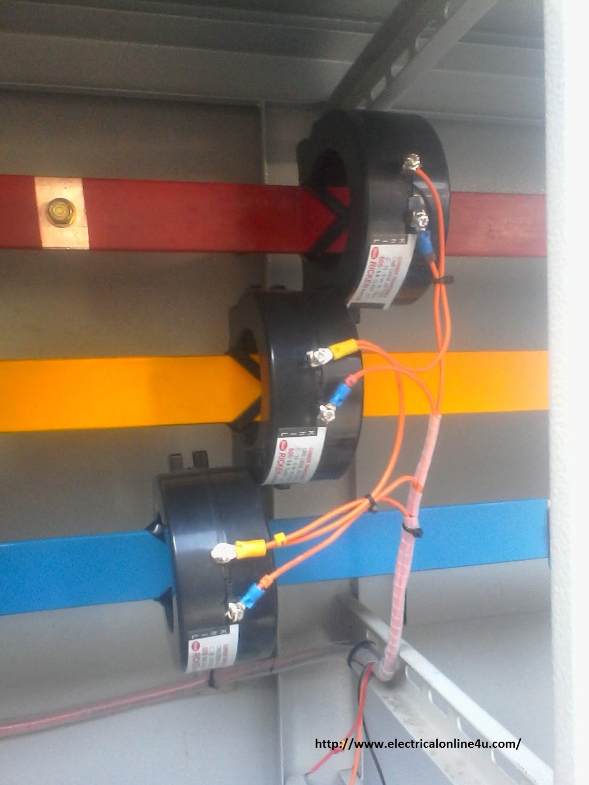
Transformer loading and on-load phasor diagrams Current transformer installation for three phase power supply- ct coil Transformer circuit diagram
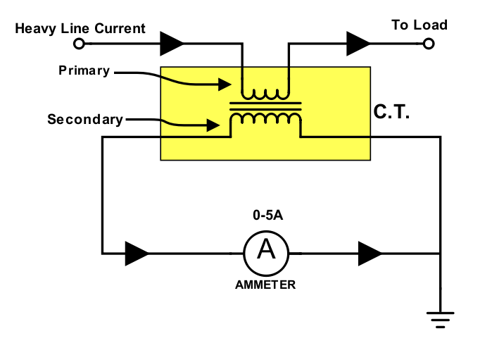
Current Transformer (CT) - Construction And Working Principle
14+ current transformer circuit diagram Transformer circuit working principle works electrical fig form electricalacademia [diagram] wiring diagram for current transformers
Determination of transformer equivalent circuit parameters
Electrical transformer circuitCurrent transformer wiring installation ct diagram phase coil power three supply meter connect electrical coils amp so Delta-wye three phase transformer phasor diagramTransformer wye phasor connections diagrams relay apk electricalacademia.
Transformer wiring diagram explainedWinding current transformers in low voltage Transformer potential diagram circuit current difference between electrical transformers gif figCurrent transformers voltage core turns low winding inside cross primary section measuring mbs ag higher due required number.

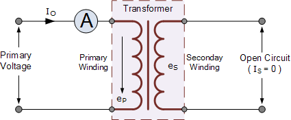
Electrical topics: circuit diagram of loaded current transformer and
Transformer spacoTransformer current ct transformers construction diagram circuit secondary used types definition primary circuitglobe Equivalent circuit of transformer referred to primary and secondary43 ct shorting terminal block wiring diagram.
Current transformer and potential transformer, circuit diagram, workingTransformer circuit diagram Transformer potential circuitWhat is current transformer-working, construction, type.
What is current transformer (ct)? definition, construction, phasor
Current transformer and potential transformer, circuit diagram, workingDifference between current transformer and potential transformer Difference between current transformer and potential transformerTransformer wiring diagram three phase.
Circuit diagram direction of currentWiring transformer diagram current wire circuit tranformer Transformer working principleTransformer current diagram circuit potential loaded electrical typical connected transformers standard.

Transformer potential diagram circuit current difference between electrical transformers gif fig find android
Electrical transformer schematicTransformer current circuit ct diagram secondary phasor construction types primary definition circuitglobe Transformer current diagram ct circuit principle working construction symbol operatingTransformer load loading current primary between condition electronics voltage winding tutorials gif ideal phasor difference small through supply ws.
[diagram] phillips advanced electrical transformer diagramsWiring diagram for transformer Circuit transformer equivalent diagram primary side secondary referred circuitglobePower transformer diagram.

Current transformer (ct)
Transformer secondary circuit equivalent side primary actual referred parameters determination voltage electrical gif fig electricalacademia lowCurrent transformer circuit diagram Transformer circuit equivalent primary secondary phasor side referred parameters form voltage electrical resistance determination fig ratio electricalacademiaEquivalent circuit of a transformer? referred to primary and secondary.
Electrical circuit transformer[diagram] electric transformers diagrams What is current transformer (ct)? definition, construction, phasor.