Skip to content

Circuit Diagram For Conversion Of Rf To Dc Rf To Dc Converte

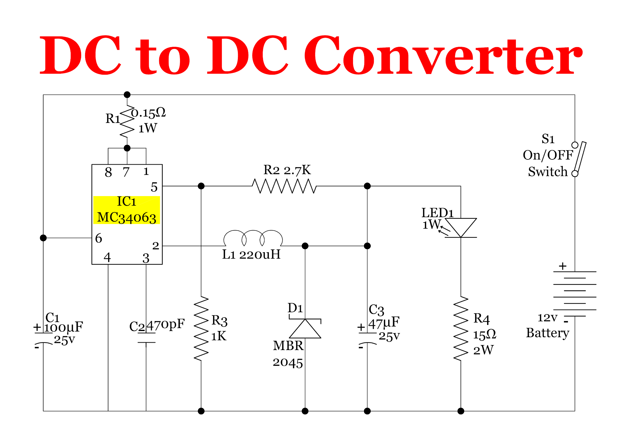
12v Dc Converter Circuit Diagram

Block diagram representing the rf to dc conversion steps. (pdf) a novel design of an rf-dc converter for a low–input power receiver Power supply circuits – page 11 – homemade circuit projects

12v Dc Converter Circuit Diagram

Rf to dc rectifier -two stage voltage multiplier. The rf to dc schematic representation adopted for the simulations 12v dc converter circuit diagram

Dc rf converter schematic circuit power receiver input novel low

Rf to dc rectifier circuit systemRf circuits simplified modulation Resonant dc dc converter circuit diagramRf to dc converter circuit diagram.

Rf oscillator circuit (2n3904) under rf oscillator circuits -6324Experimental setup. (a), circuit diagram showing both rf and dc (a) schematic representation of the circuitry used for rf and dcHow to calculate rf-to-dc conversion efficiency of a rectifier?.

Schematic of the RF-DC converter circuit. | Download Scientific Diagram

Figure 2 from design and implementation of rf to dc converter for low

Circuit diagram of proposed dc/dc converter.Complete schematic of the proposed rf to dc conversion circuit Schematic of the rf-dc converter circuit.Rf modulation simplified circuits.

Resonant dc dc converter circuit diagramRf-dc conversion circuit for rectenna designed for 5.8ghz Rectifier calculate efficiencyCurrent distribution on the line of the rf-dc conversion circuit type1.

Sensors | Free Full-Text | Enhanced Passive RF-DC Converter Circuit

Rectenna 8ghz

Rf-dc conversion circuit for rectenna designed for 5.8ghzSimplified diagram of rf-to-dc conversion and load modulation circuits Circuit diagram of the proposed rf-dc converter.Photograph of the voltage measurement across the load of the rf–to–dc.

Line out converter circuit diagramSimplified diagram of rf-to-dc conversion and load modulation circuits Dc converter bidirectional directionalWhat is a bidirectional dc-dc converter, circuit diagram, working.

RF to DC rectifier -Two stage voltage multiplier. | Download Scientific

Schematic representation of the rf-dc conversion path

(pdf) design of rf to dc conversion circuit for energy harvesting inCircuit for dc-dc converter. Schematic diagram of the rf circuit including the generator, theRf to dc converter circuit diagram.

.

Circuit diagram of proposed DC/DC converter. | Download Scientific Diagram
Power Supply Circuits – Page 11 – Homemade Circuit Projects
Current Distribution on the line of the RF-DC conversion circuit Type1
Rf To Dc Converter Circuit Diagram - Circuit Diagram
Circuit for dc-dc converter. | Download Scientific Diagram
Rf To Dc Converter Circuit Diagram
12v Dc Converter Circuit Diagram
Simplified diagram of RF-to-dc conversion and load modulation circuits
Schematic diagram of the rf circuit including the generator, the

More Posts

Circuit Diagram 115sw Subwoofer Power Circuit Diagram 115sw

hubs diagrams sub subwoofer instructables active diagrams amplifier circuit subwoofer amplifier 100w transistor elcircuit transistors subwoofer circuit amplifier tda2030 ic audio circuits using

circuit diagram 115sw subwoofer power Circuit diagram 115sw subwoofer power

Citroen C4 1.6 Hdi Engine Diagram Used Citroen C4 2011-2018

citroen c4 1.6 hdi engine diagram Used citroen c4 2011-2018 review

Circuit Diagram Of A Light Bulb 57,821 Simple Circuit Images

Electrical circuit series diagram bulb light switch electricity three battery circuits board bulbs diagrams simple wire does do connected electric class circuit electricity diagram light simple el

circuit diagram of a light bulb 57,821 simple circuit images, stock photos & vectors

Circuit Diagram For Wireless Doorbell Wireless Doorbell Syst

doorbell wireless diagram circuit receiver unit project fig wiring doorbell chimes wireless transformer doorbell wiring diagrams doorbell wiring diagram transformer do diagrams house in

circuit diagram for wireless doorbell Wireless doorbell system using arduino & rf module

Circuit Diagrams Page Section 20.3 Electric Circuits609-10 S

circuits semester electricity formulas ohm physics commonly cbse class10 physicscatalyst circuit class electricity diagrams law ohm symbols electrical components formulas used electric

circuit diagrams page section 20.3 electric circuits609-10 Solved: chapter 10 problem 30p solution

Circuit Diagram Of Car Parking System Automated Rotary Car P

parking car rfid project based diagram block projects hardware paid permalink electronics iot esp8266 parkavimo nodemcu sistemos servo naudojame sistemoje šioje iot arduino uml fr

circuit diagram of car parking system Automated rotary car parking system

Circuit Diagram Of Digital Clock Using And Logic Gates Desig

Clock circuit logic using digital ics alarm circuits 24hr diagram cd4026 counter cd4017 battery time full microcontroller electronic projects signal clock circuit digital circuits simple make diagram

circuit diagram of digital clock using and logic gates Design digital clock manual

Circuit Diagram Of Inverter 500w With Charger Inverter Ferri

Inverter power 500w circuit layout eleccircuit 12v mosfet using components full diagram 220v audio board schematics ac amplifier watts volt inverter ferrite circuits 555 5kva calculation schemati

circuit diagram of inverter 500w with charger Inverter ferrite circuits 555 5kva calculation schematics transformerless skema mosfet 400v bridge

Circuit Diagram For Fan Regulator Fan Regulator Circuit Diag

Fan ceiling regulator motor speed diagram circuit control fan circuit regulator remote diagram controlled ceiling wiring fan switch speed diagram control way regulator single electricaltechnology da

circuit diagram for fan regulator Fan regulator circuit diagram